.png)

Technical drawings are the blueprint of manufacturing. They communicate design intent to the shop floor, specifying how a part should be fixtured, which dimensions are critical, how tolerances should be applied, and how inspection should be carried out.
Without accurate drawings, manufacturers are left guessing. A missing tolerance, an unclear datum, or a misapplied annotation can cascade into rework, delays, and wasted cost. Drawings remain the essential communication tool that connects design to production.
The typical process looks like this:
Drafting is tedious, largely manual, and prone to mistakes. Even modern CAD tools struggle with simple dimensioning, let alone full GD&T workflows. Worse, this work is done by highly skilled (and expensive) engineers, pulling them away from actual design only to spend 30–40% of their time on repetitive drafting.
This results in higher development costs, longer time to market, and a constant risk of manual errors.
Over the years, there have been many attempts to automate technical drawings. All have failed for a simple reason: this is not an easy task. Previous approaches have been either Neural-net based or heuristic based. Neural nets don't work because of their essential statistical nature (engineering requires precision and accuracy). Heuristic based methods are too limiting and brittle. None can replicate the numerous judgment calls engineers make when choosing datums, applying tolerances, or aligning drawings with manufacturing methods.
Foundation EGI takes a fundamentally different approach. Instead of treating drawings as a static output, we treat them as programmable logic. Using our domain-specific language (DSL) framework and purpose-built AI models, we convert the process of creating GD&T drawings into structured, verifiable programs.
EGI works in two stages:
1. Generation
EGI automatically detects critical features from a 3D model, programmatically applies GD&T annotations, and generates a 2D drawing. Our small, tuned models require only a modest dataset (dozens, not thousands) of past examples to learn effectively.
Crucially, EGI doesn’t just create views and place dimensions. It identifies datums, predicts tolerances, and recommends process-appropriate specs, just as an experienced engineer would.
2. Modification
Still, no engineer is perfect, and no system should be expected to be. EGI is not a one-shot replacement for human expertise. Its goal is to produce an 80%+ complete draft, leaving the final review and adjustments to the human engineer.
Through natural language, engineers can refine, correct, or expand on the initial output, just like giving feedback to a junior engineer. Unlike a human engineer, however, every adjustment feeds back into the system, allowing EGI to improve continuously.
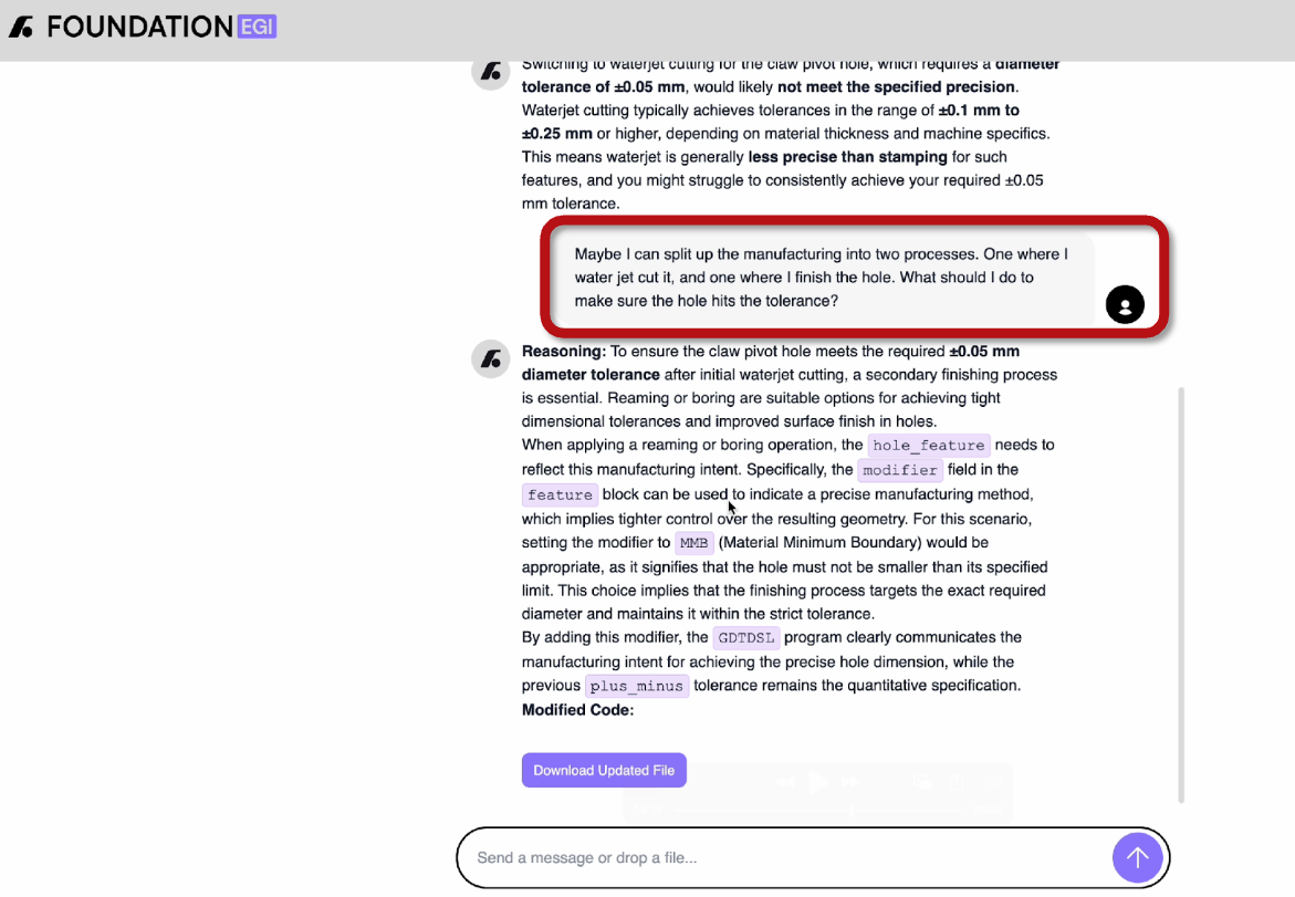
EGI also acts as a DFM companion for the designers. Manufacturing is complex, and no designer can have perfect knowledge of all the manufacturing processes out there. Instead of lengthy back and forth with manufacturing engineers, designers can use EGI as a copilot to help them with critical design decisions (“what tolerance can I achieve on this section if I use stamping?”, “Do I need to add a machining step?”, etc.). This improves iteration cycles and ensures that the products are being designed closer to what can be achieved in the real world the very first time.
Model-Based Definition is often positioned as a replacement for GD&T. But in reality, MBD doesn’t eliminate the decision-making process behind drawings. It only changes the format. Engineers still need to decide which features are critical, which tolerances are achievable, and how to fixture and inspect a part.
EGI supports MBD natively. Our system makes those critical decisions in 3D, then outputs them into 2D or MBD formats as required.
Technical drawings will always be part of engineering. But they don’t need to be a burden. With EGI, they become fast, accurate, and largely automated while keeping engineers in control of the decisions that matter.
Automating GD&T drawings with EGI means:
If you’re still creating technical drawings manually and want a better way, reach out to us at info@foundationegi.com.